Technical info.

Friday, January 31, 2020

Kadane’s Algorithm - Maximum subarray

Kadane's algorithm

Finding the sum of contiguous sub-array within an array of numbers  is called by Kadane's algorithm.

The intuitive algorithm is check the all the sum of sub-array and choose the largest sum.
Here's the code which can get the maximum sum of sub-array.


 1
 2
 3
 4
 5
 6
 7
 8
 9
10
11
12
13
14
15
16
17
18
19
20
21
22
23
24
25
26
27
28
29
30
#include <stdio.h>

int getMaxSumSubArray(int *arr, int length) {
  int sum = 0;
  int maxSum = 0;
  int start = 0;
  int end = 0;
  // i is the subarry start point
  for (int i = 0; i < length; i++) {
    sum = 0; // Reset sum when array start is changed.
    for (int j = i; j < length; j++) {
      sum += arr[j];
      if (sum > maxSum) {
        maxSum = sum;
        start = i + 1; // Start from 1
        end = j + 1; // Start from 1
      }
    }
  }
  printf ("The maximum sum of sub-array is %d\n", maxSum);
  printf ("The maximum sum of sub-array starts from %d to %d\n", start, end);
  return maxSum;
}

int main() {
  int inputArray[] = {-1, -5, 3, -2, 4, 5, 2, 7, 4, 3, -9, 5, 3, 6, -9, -3};
  // Get a length of the inputArray
  int arrayLength = (int) (sizeof (inputArray) / sizeof (int));
  getMaxSumSubArray(inputArray, arrayLength);
}

The result of the this code is shown below.


The maximum sum of sub-array is 31

The maximum sum of sub-array start from 3 to 14

This intuitive algorithm is not the best and we can change it more efficiently.
The start sub-array index can be determined without checking all the sum of the sub-arrays and the idea is that the sub-array sum is start from the first index and re-start the sub-array summation when the sum is negative value. Because if the sum is negative in the middle of summation, the next sum is less than the next value so we have to start from the next value to get a maximum sum of the sub-array.

Here's the final code.


 1
 2
 3
 4
 5
 6
 7
 8
 9
10
11
12
13
14
15
16
17
18
19
20
21
22
23
24
25
26
27
28
29
30
31
#include <stdio.h>

int getMaxSumSubArray(int *arr, int length) {
  int sum = 0;
  int maxSum = 0;
  int start = 0;
  int end = 0;
  // i is the subarry start point
  for (int i = 0; i < length; i++) {
    sum += arr[i];
    if (sum > maxSum) {
      maxSum = sum;
        end = i + 1; // Start from 1
    }
    if (sum < 0) {
      sum = 0;
      start = i + 1; // Strat from the next item
      start += 1; // Start from 1 
    }
  }
  printf ("The maximum sum of sub-array is %d\n", maxSum);
  printf ("The maximum sum of sub-array starts from %d to %d\n", start, end);
  return maxSum;
}

int main() {
  int inputArray[] = {-1, -5, 3, -2, 4, 5, 2, 7, 4, 3, -9, 5, 3, 6, -9, -3};
  // Get a length of the inputArray
  int arrayLength = (int) (sizeof (inputArray) / sizeof (int));
  getMaxSumSubArray(inputArray, arrayLength);
}

The result of the this code is shown below. That's the same as the result of the intuitive algorithm.


The maximum sum of sub-array is 31

The maximum sum of sub-array start from 3 to 14

#Kadane, #algorithm, #MaximumSubarray


Friday, July 15, 2016

ESP8266 tutorial 3 - ESP8266 flash boot and AT command mode operation.

Previous topic.


If you have downloaded NONOS SDK binary in your ESP12E board, the next step is run and test EPS12E board.

Step 1 : Setup ESP12E board as shown below and turn ON EPS12E board.

To run ESP12E board, we should configure SPI flash boot mode using GPIO 0, 2, and 15

GPIO15
GPIO0
GPIO2
Mode
Description
L
L
H
UART
Download code from UART
L
H
H
Flash
Boot from SPI flash
H
X
X
SDIO
Boot from SD-card


Step 2 : Run serial monitor program.

I tried to use putty as a serial monitor program. But I can't find proper setting to see serial message from ESP12E board. So I can't use putty for ESP12E board now. If you have any idea about it. Please let me know.
Now I'm usgin serial monitor program in PlatformIO, I can see serial message from ESP12E with default setting.
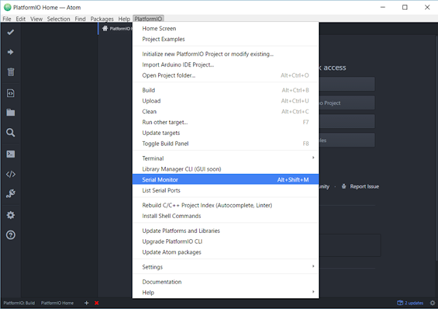
You can find serial monitor tool in PlatfomIO menu.

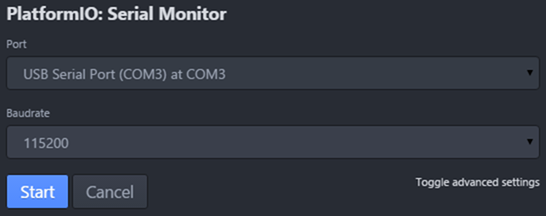
Here's the COM port setting, the baud rate is 115200.


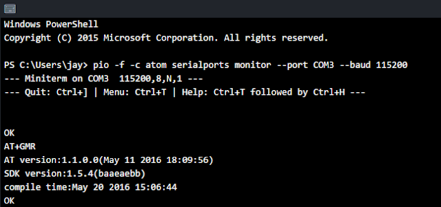
Step 3 : Type AT command in serial monitor.

Tyep AT+GMR for test, AT+GMR command show the version information

If you can see the version information properly, now you can do everything through AT Command.
Please read AT command manual of ESP8266 in here

Wednesday, July 13, 2016

ESP8266 tutorial 2 - UART Firmware download

Previous topic.


If you just got the ESP12e board. You don't have any idea what you do to use it.
I think the first step is downloading firmware which you want to use.

Using the ESP8266 firmware download tool, you can easily download the official SDK firmware.

Before downloading firmware you should prepare followings.
  1. 3.3V DC power. You can use power supply if you are in the lab. But if you don't have it, you can use 3.3V regulator board (like this board)
  2. PC USB to UART converting board is needed. I'm using UM232H-B board (Here's the datasheet of UM232H-B)
  3. ESP8266 download tool. You can download it in here.
  4. Breadboard and wires to make circuit.

When you are ready to prepare upper four items. Let's start downloading.

Step 1) Make circuit like following picture.

GPIO0, 2, and 15 are used to select boot mode of ESP8266. this setting is for UART download mode.

This table shows three different boot mode of ESP8266.

GPIO15
GPIO0
GPIO2
Mode
Description
L
L
H
UART
Download code from UART
L
H
H
Flash
Boot from SPI flash
H
X
X
SDIO
Boot from SD-card

Step2) Connect UM232H-B board to PC USB port and power on 3.3V DC power supply.

You should check the COM port number through "Device Manager" in Control panel. In my case, COM3 will be used for ESP8266 communication.


Step3) Run ESP flash download tool on the PC


Step 4) Click "Start" button.

You can see the some information through CMD window and DETECTED INFO and MAC Address in the GUI.
If you can't see the DETECTED INFOR and MAC Address in the GUI and see the FAIL message, your circuit has issue or your esp12e board has issue. Please check them again.


Step 5) Download firmware on the web.

You can find SDKs in this web page
I'll download latest NONOS_SDK in this web page

Step 6) Set the address of bin files

you can find the source and bin files in SDK. I'm not build source code now. I'll download bin file to my ESP12e board. Please open "README.md" file in "ESP8266_NONOS_SDK\bin\at"
And then, find NON-BOOT mode section.
ESP12e has 32Mbit Flash. So I'll use 32Mbit case in this document. (I don't know the difference of 32Mbit mode and 32Mbit-C1 mode. I just tried to 32MBit mode)


According to the README.md file, I can set the address of bin file which I should download into my ESP12e board.

Step 7) Download firmware

Please check the following picture and click "start" button" in order to download firmware.


Step 8) Check whether the downloading is done without any issue.

you can see the Finish message in GUI. The download works well.
I'll explain how to test the downloaded firmware in next article.


If you want know more about the ESP8266 SDK. Please refer to this document.

Tuesday, July 12, 2016

Node.js tutorial 5 - What's JSON?


JSON specification is described in ECMA-404. you can easily find it in here
The specification also very simple, the real contents are in only 5 pages.

Here's one of the example JSON data. I'm copied from Wiki page. For more information, please visit JSON wiki page


Not only the machine which treat this data but also you can read it and understand the meaning of data.
{
  "firstName": "John",
  "lastName": "Smith",
  "isAlive": true,
  "age": 25,
  "address": {
    "streetAddress": "21 2nd Street",
    "city": "New York",
    "state": "NY",
    "postalCode": "10021-3100"
  },
  "phoneNumbers": [
    {
      "type": "home",
      "number": "212 555-1234"
    },
    {
      "type": "office",
      "number": "646 555-4567"
    },
    {
      "type": "mobile",
      "number": "123 456-7890"
    }
  ],
  "children": [],
  "spouse": null
}

Wednesday, July 6, 2016

ESP8266 tutorial 1- introduction of esp8266(esp12e) Wifi module for IoT

Wireless network is essential for IoT device, so we should choose one of the wireless network solution among WiFi, Bluetooth or any others.
The most popular wireless networks are WiFi and BLE and there's pros and cons.
Bluetooth BLE is best for power consumption but it need BLE gateway to communicate through internet. If you are not familiar with BLE gateway, please see following product information.

BEL gateway product, iGS01.
Product information : ingics.com homepage
BLE gateway (from ingics.com homepage)

I think you don't have BLE gateway in your home work workplace because it's not common device. so I think it is the one of the disadvantage of BLE network for IoT.

WiFi network is very common and we can easily find WiFi AP at home or work place. so low power WiFi is better than BLE for simple IoT network. The low cost and low power WiFi module for IoT is ESP8266 module.

There are many types of ESP8266 module and you can choose one of them according to your IoT device spec. you can find all kind of ESP8266 module in following website. As far as I know, esp12e is popular now and you can buy it through internet very easily.

ESP8266 module - following table is from this web page.

Board IDpinspitchform factorLEDsAntennaAnt.SocketShieldeddimensions mm
ESP-018.1“2×4 DILYesEtched-on PCBNoNo14.3 x 24.8
ESP-028.1”2×4 notchNo?NoneYesNo14.2 x 14.2
ESP-03142mm2×7 notchNoCeramicNoNo17.3 x 12.1
ESP-04142mm2×4 notchNo?NoneNoNo14.7 x 12.1
ESP-055.1“1×5 SILNoNoneYesNo14.2 x 14.2
ESP-0612+GNDmisc4×3 diceNoNoneNoYes?
ESP-07162mm2×8 pinholeYesCeramicYesYes20.0 x 16.0
ESP-08142mm2×7 notchNoNoneNoYes17.0 x 16.0
ESP-08 New162mm2×8 notchNoNoneNoYes18.0 x 16.0
ESP-0912+GNDmisc4×3 diceNoNoneNoNo10.0 x 10.0
ESP-1052mmm?1×5 notchNoNoneNoNo14.2 x 10.0
ESP-1181.27mm1×8 pinholeNo?CeramicNoNo17.3 x 12.1
ESP-12162mm2×8 notchYesEtched-on PCBNoYes24.0 x 16.0
ESP-12-E222mm2×8 notchYesEtched-on PCBNoYes24.0 x 16.0
ESP-13181.5mm2×9?Etched-on PCBNoYes? x ?
ESP-14222mm2×8 + 61Etched-on PCBNoYes24.3 x 16.2
WROOM-02181.5mm2×9NoEtched on PCBNoYes20.0 x 18.0
WT8266-S1181.5mm3×61Etched on PCBNoYes15.0 x 18.6

Friday, February 5, 2016

nRF51 DK for IoT development with Bluetooth low power

I had a change to get the NRF51 DK board and test it. I think it's GREAT. The board size is similar with Raspberry Pi B+ but the computing power is less than Raspberry Pi.
The nRF51 is designed for IoT controller with Bluetooth low power (BLE). It has nRF51422 chip which has ARM Cortex-M0 32bit, 256k flash memory, 32k  sram and 2.4GHz transceiver which support BLE, ANT+ and other 2.4GHz RF.


BLE is most popular connectivity interface for IoT platform. So nRF51 DK board is best for IoT device. It has many document and examples on the web-site and the community is very popular.

The BLE and 2.4GHz RF is controlled by SoftDevice library. and the application can use it through API. So anyone who is not familiar with BLE can easily handle it.

It has J-Link debugging interface so you can use J-Link debugging tools without any other J-Link HW and It is mbed enabled device. That means you can control nRF51 device using ARM mbed platform.

If you are interested in this board. please visit following links.

nRF51-DK official page
 - You can download document and SDK in this site.

ARM mbed - nRF51-DK page


Wednesday, August 26, 2015

Node.js tutorial 4 - Run Node.js in visual studio 2015

Previous topic
Node.js turorial 1 : Node.js install on windows
Node.js tutorial 2 - Visual studio community 2015 for Node.js

Node.js tutorial 3 - Let's start Node.js with Visual studio

You can run the node.js command in visual studio. Please see following steps.

Step 1 : Open Node.js interative windows as followings


Step 2 : Let's play Node.js in Node.js interactive windows


Now, you can use node.js interactive window in Visual Studio.